CONSTRUCTION


Self-Reversing Threaded Shaft
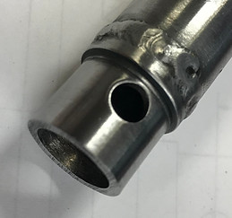
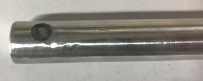
The trial run was done on aluminum to prove that the double threaded path could be made. High burrs formed ( ) and the tool pullout was unsuccessful ( ) but the overall cross-threaded path was successful on the CNC lathe.
Forged from 1/2” steel rod, the shaft is cut using the CNC lathe. The part is faced clamping less than 0.4” of the shaft. Tools are switched and the CNC program starts the path at the end of the thread slowly turning down the thread depth by .002" with each path. The path will reach a certain point then turn back creating a cross threaded path. This path is cut the spec depth. All burs are removed from the edges of the path to ensure smooth travel of the ball bearings and ball nut.
Trial Run

Self-reversing threaded shaft

Ball Nut
Forged from 7/8” steel rod, the ball nut is made on a manual lathe and mill. A hole is drilled to a diameter of 31/64" and reemed to 1/2". The part is faced and reduced to the diameter of the shoulder. The front is further reduced to form the shoulder of the part. A groove tool is used to form the 3 grooves on the front to the specified depth. A parting tool is used to reduce the back OD to spec. The manual mill plunges the single bearing hole. The part is then rotated 45° from the single bearing hole using a lathe chuck setup. The slot is plunged through at the middle and milled all at once. The chuck is rotated 90 degrees from its previous spot and the same process is used for the second slot on the opposite side. All burs are remover and the band saw then removes the part from stock. The large base is welded to the adapter tube.

Ball Nut

Adapter Tube
Forged from 1” round tube with 0.12" wall thickness, the tube is made on the manual lathe. The tube is faced as needed and the OD is reduced to spec. Because both the adapter and ball nut will be welded completely around the diameter of this tube, the piece is removed from stock with a parting tool and all burs are removed.
Adapter Tube


Adapter
Forged from 7/8” steel rod, the adapter is made on a manual lathe and mill. A hole is drilled to a diameter of 9/16". The part is faced and reduced to the diameter of the shoulder. The front is further reduced to form the shoulder of the part. A parting tool is used to reduce the back OD to spec. The manual mill drills the single pin hole through the part. All burs are removed and the band saw then removes the part from stock. The large base is welded to the adapter tube.
Adapter


Press Fit Cover
Forged from a ¾” diameter aluminum rod, the cover is drilled to a hole diameter of 47/64” on a manual lathe. The part is then faced as needed and the ID is chamfered at the end. A square form tool separates the part from the rod. The mechanical press forces the cover to the ball nut proceeding the insertion of the ball bearings and O-rings.
Press Fit Cover


Drive Shaft
Drive Shaft


The shaft is a standard size, 3' long 9/16" aluminum rod. The ¼” hole is drilled though using the manual mill using a ¼” drill bit. The part is flipped and the pin connecting side slots are milled using a 3/8" end mill. the part is rotated and the 1/4" hole is drilled. The end fillets are grinded to an appropriate curve. All burs are removed with the soft grinder.
